Phase 1 · 40–80 km/h · JetsonPhase 2 · 300–500 km/h · FPGA

Sensor fusion payload.

Radar, thermal camera, IMU and barometer fused on board to estimate position without GPS.
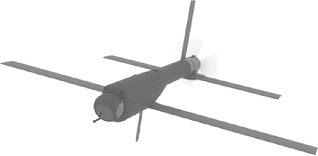
The host autopilot always flies the aircraft.

01 · Position fix

Drift, then a terrain fix.

Inertial estimates drift between fixes. A radar ground profile matched to the stored map pulls the estimate back.

Flight · drift and terrain fixesPhase 1 · 54 km/h
The aircraft flies left to right. Its inertial estimate drifts away from the true track inside a growing uncertainty envelope, and each radar terrain fix pulls the estimate back.
Since last fix
0 s
Position error
0 m
Profile collected
0.0 / 1.5 km
Fixes
0
  • True position
  • Our estimate (offset drawn 5× larger)
  • Uncertainty
  • Radar ground samples
  • Terrain fix
  • Runs 14× real time

Concept illustration · generic units · state estimates and advisories only. No engagement logic or weapon effects.

02 · Waypoint navigation

Waypoint navigation by terrain matching.

The aircraft follows the planned route. Terrain matches correct its position estimate.

Route with stored terrain references0.0 / 10.0 km
Aircraft follows four navigation checkpoints over a stored elevation map. Radar samples the terrain below it. A hollow aircraft marks the navigation estimate.
  • Aircraft
  • Planned route
  • Radar profile
  • Position estimate
  • Terrain match
Synthetic along-track example. Thermal scene matching adds a separate cross-track check. The host autopilot flies the route.

Concept illustration · generic units · state estimates and advisories only. No engagement logic or weapon effects.

03 · Sensors in

Sensors in, position out.

Every sensor reading is time-stamped, cleaned and fused on a Jetson in Phase 1, or on an FPGA system-on-chip in Phase 2.

View payload components
Sensors in · Processing core · OutputsPhase 1 · Jetson

Sensors in

  • IMU200 Hz
  • Barometer25 Hz
  • Radar alt40 Hz
  • Imaging radarPhase 2 · not fitted yet
  • Thermal cameradown · terrain picture, ~300 m
  • Airspeed10 Hz
  • GPScheck only · never used to navigate

Processing core

JetsonAll software on the CPU
  1. 1Time-stamp + cleanOne clock from the GPS pulseCPU
  2. 2Predict motionFrom the IMU, 200 times a secondCPU
  3. 3Ground profileOne height every 25 mCPU
  4. 4Radar map matchProfile vs terrain mapCPU
  5. 5Thermal scene checkPicture vs reference sceneCPU
  6. 6Update estimateAlong + cross-trackCPU

Health: all sensors fresh · logging

Outputs

  • Position estimateEstimate ± uncertainty
  • Position fixRadar + thermal agree
  • Course correctionautopilot steers
  • Processing delayvaries · 10 ms target
  • To the autopilotSigned serial
Sensor traces are simulated.

Concept illustration · generic units · state estimates and advisories only. No engagement logic or weapon effects.

04 · Filter

How the filter works.

The navigation filter tells the radar how the aircraft is moving, so each ground profile is assembled in the right place.

Navigation filter · EKF · 200+ HzIllustration, not to timing scale
Radar, radar altimeter and IMU data flow through FPGA logic into the map match and the navigation filter. The filter feeds velocity and attitude back to the radar processing and sends position to the autopilot link and flight controller. FPGA logic · fixed timing ARM cores velocity · unwraps Doppler attitude · corrects beam angle Imaging radarraw radar data Radar alt40 Hz IMU + baro1 kHz Range FFTdistance Speed FFTDoppler Angle FFTdirection Height grid2D patch Time-stamp≤ 0.1 ms Height samplesevery 25 m Map matchevery position at once Time-stamp≤ 0.1 ms Navigation filterEKF · 200+ Hz Autopilot linkposition out Flight controllerflies the aircraft
  • Radar data
  • IMU data
  • Filter feedback
  • Fix / position out
Overview · 5 steps Radar is sharp The filter sends our speed and attitude back. Fast ground echoes (21–36 m/s at the beam edge) unwrap correctly, so every radar frame adds to the fix.
Step 0 of 5

Also on the chip: thermal clean-up (FPGA) · mission logic + collision avoidance (ARM) · AI models on the AI engines or a small Jetson.

Concept illustration · generic units · state estimates and advisories only. No engagement logic or weapon effects.

05 · On board

What's on board.

Select a part of the carrier board to see its job in the Jetson and FPGA versions.

96 × 80 mm · top viewSENZFUSION NAV CARRIER · REV A
U1 on socket J1

Jetson module

Jetson job
Runs every navigation step: sensor drivers, radar and thermal matching, the filter and logging.
FPGA job
Fixed-timing logic stamps every reading, runs the radar FFTs and map matching. Its ARM cores run the filter.
Electronics power≈ 50 Wpreliminary

Concept illustration · generic units · state estimates and advisories only. No engagement logic or weapon effects.

06 · Rollout

Phase 1: prove it at 40–80 km/h.

  • IMU

    Tracks motion

    Keeps the position going between fixes.

  • Barometer + radar

    Measures the ground

    Gives the height of the ground below the aircraft.

  • Radar + thermal

    Finds the aircraft on the map

    Radar matches the ground profile. Thermal confirms it and fixes sideways drift.

Earn trust in four steps

GPS stays on board for timing and checking. It never navigates.

  1. Step 1

    Record

    Fly on GPS. Test the navigation afterwards.

    Flies on
    GPS
    Jetson
    Offline
  2. Step 2

    Shadow

    Run live next to GPS. Compare. Don’t steer.

    Flies on
    GPS
    Jetson
    Live, watching
  3. Step 3

    Closed loop

    Fly on the fused estimate. GPS on standby.

    Flies on
    Jetson
    GPS
    Backup
  4. Step 4

    GPS off

    Whole legs without GPS.

    Flies on
    Jetson
    GPS
    Off

07 · Swarm

A local GPS for the swarm.

Two navigator drones carry the fusion payload. The other eight range to them over UWB and share their fused position as a reference.

UWB ranging to both navigatorsActive NAV-A
Navigator drones NAV-A and NAV-B on either side of eight guided drones, G1 to G8. Every guided drone ranges to both navigators over UWB. The active navigator holds the token and sends the reference; the standby navigator cross-checks. G1 G2 G3 G4 G5 G6 G7 G8 NAV-Aactive NAV-Bstandby
Active
NAV-A
Other
NAV-B · hot standby
Log
NAV-A holds the token
  • Reference from active · 20 Hz
  • Standby cross-check · 5 Hz
  • UWB ranging to both navigators
  • Navigator token
Rates slowed for display

  • Fast handover: the standby already computes a full solution, so taking over is a token change.
  • Second opinion: if the two navigators disagree, that is a stronger fault signal than UWB alone.
  • Two anchors: ranging to both navigators, on opposite sides, gives much better geometry.

Concept illustration · generic units · state estimates and advisories only. No engagement logic or weapon effects.

08 · Swarm stack

Swarm service software stack.

The same build runs on all ten drones. Messages climb up the stack; commands come back down.

The per-drone software stack in three bandsMESSAGES UP · COMMANDS DOWN
  1. Applications

    NAVIGATORS ONLY
    • SenzFusion service — navigators only: fused fix → shared reference
    • Swarm app — formation · task allocation · handover · fault check

    e.g. a nav drone's fix becomes the reference; 5 of 8 flag NAV-A → token moves to NAV-B

  2. Trust

    • Policy gates — session · freshness · rate · role · plausibility
    • Identity — hardware keys · certificates · revocation

    e.g. a stale or revoked drone's data is dropped before it can steer the swarm

  3. Transport

    • UWB ranging · autopilot bridge
    • Encrypted tunnels to each of 9 peers
    • IP transport · signed messages · mesh multi-hop

    e.g. G4's packet hops through G6 to reach NAV-B

RADIO · AUTOPILOT SERIAL — HARDWARE everything above this line is the same build on all ten drones

What actually flows — shared odometry

≈ 260 B signed · position, attitude, velocity + uncertainties · slowed for display
  • Active → all 20 Hz
  • Standby → all 5 Hz
  • Each guided → navs 5 Hz

Total ≈ 0.63 Mbit/s

Concept illustration · generic units · state estimates and advisories only. No engagement logic or weapon effects.

09 · Mission

The mission, end to end.

  1. Concept illustration of a folded terrain map with a planned waypoint route

    01 · Prepare

    Plan and review

    Nav Drone sets waypoints and supports route-risk review and plan adjustment.
    Reviewed planNav Drone

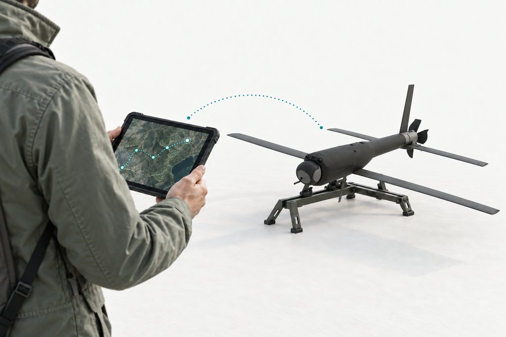
  2. Concept illustration of an operator transferring a route from a rugged tablet to a survey aircraft

    02 · Handoff

    Transfer and verify

    The planned integration transfers the approved route and references to the drone and checks readiness.
    Planned handoffOperator

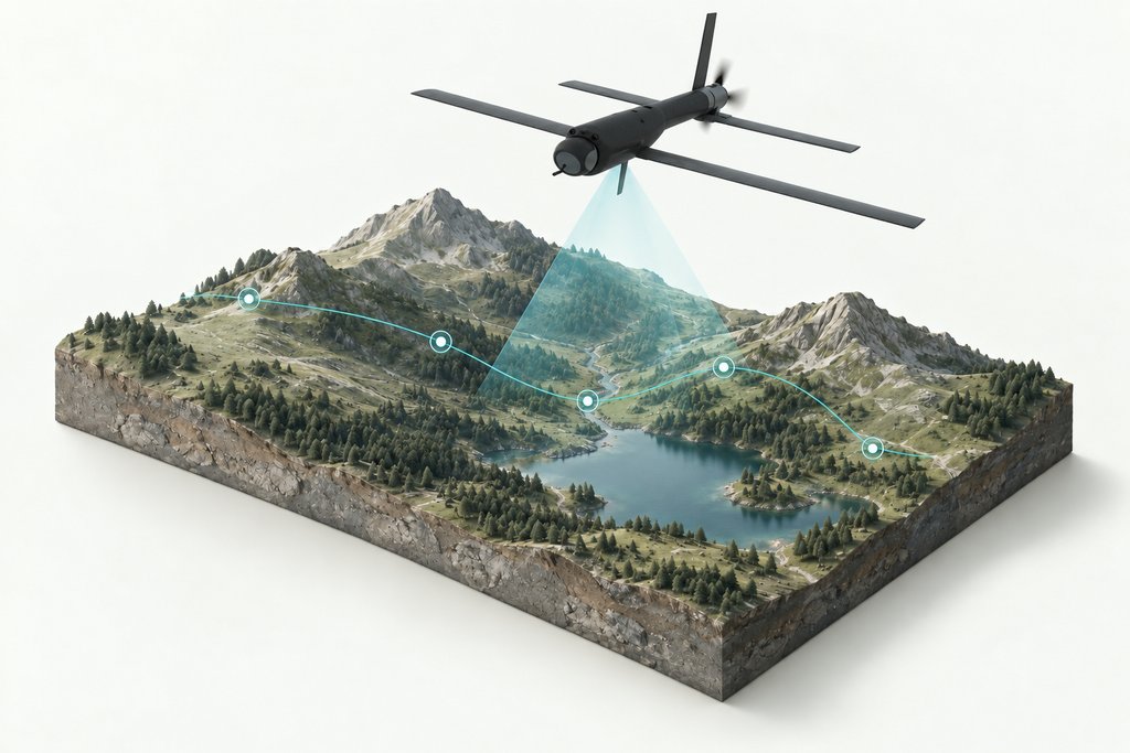
  3. Concept illustration of a survey aircraft sensing terrain above its planned waypoint route

    03 · Execute

    Navigate the route

    SenzFusion reports position fixes and uncertainty. The host autopilot flies the route.

    Estimate availableSenzFusion + host

Concept illustrations with synthetic terrain and generic units. Route-risk review and plan transfer are illustrated workflows; the combined handoff remains a planned integration.

Concept illustration · generic units · state estimates and advisories only. No engagement logic or weapon effects.

Inside the navigation payload.

Explore the payload